Thursday, October 25, 2012

REM detector + display updates (or, scrolling displays are almost as cool as fezzes)

As I remarked in a recent post, I've nailed down the cause of my pesky REM detector noise issue.  Additionally, I started sprucing up the display subsystem, using a DMA channel to significantly reduce the processor load needed.  I've taken another couple of steps forward, in that I've implemented a fix to the REM noise issue, and I've refined the display subsystem so that it can easily produce text and primitive graphics; these refinements are shown immediately below.

The bottom 3/4 of the display is the REM differential signal level, scrolling from left to right.  The numbers on top are the 32-bit integer holding the device's seconds counter (left) and the IR illuimnator level (right).

Not very interested waveform-wise, but a clearer picture.


The video shows the scrolling display in action; since the sensor is pointed at the couch arm, there's not much going on, except when I rotate it.

Implementation details, vaguely

On the display side, this is really only a slight complication of what I outlined previously; there's a local buffer that I draw on, and periodically I set the DMA channel to transmit the contents of that buffer to the display via the serial transmitter peripheral.  There's a little bit of trickery translating the signed ADC inputs into the bytes that get painted into the display buffer, but it's overall quite straightforward.  A zipped archive of the project files is here.

On the REM detector side, I'd determined that the reason I was getting 'bias noise' every four samples was that the PWM switching transients were making it into the ADC signal, and because the PWM and REM counters were not integer multiples of each other, they would only 'line up' every four samples.  To rectify this scenario, I modified the code to make sure that the sample timer is always set up to be an integer multiple of the PWM timer period.  I also set up the clocking of the timers to go through the XMEGA's event system, so that I could keep the timers in sync.  A plot of the signal below shows no abnormal patterns in the noise, so I think this has taken care of the problem.


Moving Forward again

So, my next step has to be nailing down the REM detector.  Specifically, I'm going to slightly modify the hardware so that I can quarter the PWM duty cycle.  This way, I can maximize the settling time between the PWM switching time and the ADC sample time.  After this is done, I'm going to assess whether this has had the effect of decreasing the noise; either way, I'm going to collect some real-life sleep data, and get cracking on whether I can assemble a filter/classifier that can detect REM.

Of course, this completely avoids the issue of the busted charger circuit; unfortunately, I still haven't secured access to a hot-air rework station...

Wednesday, October 24, 2012

Using DMA to automatically transfer display data (or, it's RTFM, not 'Haphazardly Cast Your Eyes Left to Right Over The Manual While Thinking of Something Else')

As an aside from the process of perfecting the REM detector, I decided to start to clean up the display-painting parts of the firmware.

It takes half a kilobyte of data to completely fill the display (128-by-32 off-or-on pixels) and the data is sent through one of the chip's serial peripherals.  Since there is so much data to transmit per display update, it takes a LOT of processor cycles to do so; it takes even more cycles to do so by waiting and polling the serial peripheral instead of setting up an interrupt (as I did to debug the display).

Since the process of getting that data out to the display could be fairly straightforward, it seemed like the perfect excuse to take advantage of the AVR XMEGA microcontroller's onboard DMA feature.  And since I made a couple of errors along the way (and couldn't find a straightforward explanation of my problem online), it seemed appropriate to describe the situation here.

What is DMA?

Briefly, DMA (direct memory access) is a way of taking the load off of the processor by 'automating' data transfers.  Specifically, the DMA controller transfers a block of data from one location in memory to another while the processor executes other tasks.  Without a DMA controller, any large data transfer would take up processor time as the processor accessed and copied each byte of data individually.

There are many situations where you would want to transfer a lot of data from one location to another, or a small amount of data from (or to) one location a great many times.  In my scenario, I have a buffer in local memory that represents what the display will look like; the buffer is local so that manipulating it (compositing the image, blanking regions, adding text) is easier.  However, that buffer data needs to be periodically sent (serially) to the display hardware.  Ideally, the DMA will automate the process of taking each byte of the buffer in turn and sending it to the serial peripheral when it's ready to accept the bytes.

Implementation on the XMEGA

The XMEGA A microcontroller that I'm using has four independent DMA channels.  Each of them has a lot of configuration, including the ability to specify the source and destination data addresses and the ability to set what triggers the data transfers.

My problem was that I didn't read the manual closely enough; I thought that setting the channel trigger to the serial peripheral meant that every time the send register was empty (the trigger source), that a single byte would be sent.  In the default mode, however, the trigger causes the DMA to transfer an entire block of data as quickly as possible; since the serial peripheral sends out bytes a LOT slower than the rate that the DMA controller pushes bytes, this meant that each transfer only resulted in a few randomly-selected bytes of the buffer actually being sent to the display.  This caused me some consternation until I re-read the manual and realized my error; this fast operation is useful when copying data into SRAM or other fast destinations, but completely inappropriate for slow, single-byte destinations like the USART peripheral.

For slower destinations which will need to signal the transmission of each byte (or each burst of 2, 4, or 8 bytes) one at a time, the 'Single-Shot Data transfer' mode is used.  This mode completes a single burst, instead of a whole block, with each DMA channel trigger activation.

Since I want to transfer the complete contents of the display buffer to a single address on the serial peripheral, I need the destination address to be fixed and the source address to increment during the transmission, and reset at the end for the next update.

The actual C code I used to initialize the DMA controller and channel on the ATXMEGA128A4U is shown below; USARTC1 is the serial peripheral I'm using as my transmitter (it's been set up in master SPI mode for my display module, and then used to initialize the display module) and debugBuffer is the 512-byte-long stretch of internal memory that I'm using as my display buffer.

//set up a DMA channel
//enable the DMA controller
DMA_CTRL = DMA_ENABLE_bm;
//set the burst length to 1 byte
DMA_CH0_CTRLA = ( DMA_CH_SINGLE_bm | DMA_CH_BURSTLEN_1BYTE_gc );
//set the following: source address incremented, reload after each block; destination address fixed (reload after each block)
DMA_CH0_ADDRCTRL = ( DMA_CH_SRCRELOAD_TRANSACTION_gc | DMA_CH_SRCDIR_INC_gc | DMA_CH_DESTRELOAD_TRANSACTION_gc | DMA_CH_DESTDIR_FIXED_gc );
//now set the DMA trigger source to the USART data register being empty
DMA_CH0_TRIGSRC = DMA_CH_TRIGSRC_USARTC1_DRE_gc;
//load the block transfer count register with the number of bytes in our blocks (that is, 128*4 = 512)
DMA_CH0_TRFCNT = 512;
//now put in the initial source address; should be the memory address of the first byte of the display buffer
DMA_CH0_SRCADDR0 = ( (uint16_t) debugBuffer >> 0 ) & 0xFF;
DMA_CH0_SRCADDR1 = ( (uint16_t) debugBuffer >> 8 ) & 0xFF;
DMA_CH0_SRCADDR2 = 0x00;
//now specify the destination address; the transmit register of the USARTC1
DMA_CH0_DESTADDR0 = (( (uint16_t) &USARTC1_DATA ) >> 0) & 0xFF;
DMA_CH0_DESTADDR1 = (( (uint16_t) &USARTC1_DATA ) >> 8) & 0xFF;
DMA_CH0_DESTADDR2 = 0x00;

Once the DMA channel is set up (and assuming the USART and display have been initialized), I can update the display with the current contents of the buffer by simply enabling the DMA channel:

DMA_CH0_CTRLA |= 0b10000000;

Thursday, October 11, 2012

Project Updates (or, I am probably not dead)

So, it recently came to my attention that I haven't posted in several months.  This is due, in large part, to my actually getting work done on my PhD.  This is also due to the fact that the next steps are relatively... un-glamorous and un-postable.  Specifically, I have a small issue with the REM detector, and I need to figure out what's wrong with the battery charger circuit.  On the up side, I was able to significantly reduce the standby power consumption of my helmet flasher so... little victories.

Charger Debugging

As it stands, the Lithium-Polymer battery charging circuit does not work.  This is ironic, as it was the only sub-circuit that I did not mock up and test before ordering the circuit boards (I even mocked up the 3.3V buck converter, which only had three components).  I did this because, well... I was just using the reference implementation.  I've gone over the design (and the physical artifact's correspondence to it) with a fine-toothed comb; at this point, I'd like to swap the chip to see if that's the issue.  Unfortunately, I do not own a hot-air rework station, so that is easier said than done.  Additionally, the chip gets REALLY hot and sources a bunch of current when you plug it in, which complicates debugging, as I can only leave it plugged in for short periods.  Further, even if I could simply replace the chip, I'd be leery of doing it, as the new chip could easily fry as well.  This is triply annoying, as I would like to add the charger to my helmet and run signal glove in their next iteration, but can't do that until I know I've got the circuit right.

REM Detector Hiccups

The specific problem with the detector is that, for certain levels of illumination, the the detector output follows a 'negative bias' for every fourth sample; this is illustrated below.  Looking at the 'noise' and mean of the signal after separating it into four down-sampled signals (that is, the first sub-signal is every four samples of the original, starting with the first sample of the whole record; the second is every four starting with the second, etc.), it appears that this really is just a constant 'bias' term added only to every fourth sample.
This is an example of the detector output against my hand; green is the differential signal, dark blue is the single-ended signal, and light blue/cyan is the illuminator amplitude.  As you can see, the signal appears to get much more 'noisy' as the illumination level increases, until it abruptly decreases at a certain level.
Zoomed in view of the 'noisy' segment from above; we see that the extra 'noise' is due to every fourth sample being much lower than the other three.  This pattern is also borne out in the single-ended signal.
My current hypothesis is that this is due to my use of low-passed PWM outputs to give myself some extra low-bandwidth analog outputs to control the REM detector illumination level and the differential signal bias level.  Specifically, since the sample-specific noise only occurs at certain levels of illumination, and then suddenly stops once the level raises above that level, I am lead to believe that it's something to do with the PWM switching time lining up with the ADC sampling time.

If that's the case, I'll have to decrease the passing of switching transients by reducing the corner frequency of the low-pass and/or increasing the carrier frequency of the PWM.  Of course, increasing the carrier frequency will reduce the resolution of the LP-PWM channels; however, since I don't use the full resolution anyway, it wouldn't be much of a sacrifice.

Helmet flash controller standby power reduction

Going back to the helmet flasher project, I noticed that the AA batteries were getting drained in a manner that was less-than-consistent with usage.  I recalled that I had been less than diligent in regards to standby power usage, so I figured I could shave off a few milliamps by taking a closer look.

There were two main methods I figured I could use to reduce standby power use: put the controller into a deeper sleep state while in standby, and modify the hardware so that I could remove power from the op-amps used int he constant-current LED drivers.

The first approach, going into a deeper sleep state, was the first I implemented since it didn't involve modifying the hardware.  Before making my changes, I inserted a 1-Ohm 1% precision resistor to measure the standby current draw.  I set the device to go into "power down" when going into the standby state, with wake-up accomplished by state change on any of the buttons.  Additionally, I set the device to go into "standby" while the timers count and wait to move on to the next flasher state.  The source is available here, in case it is useful to someone wanting to see how a non-human primate would implement the preceding.

After implementing the sleep state changes, the standby power consumption went from 2.1mA to 1.7mA.  Good, but we're not finished.  Since the on-state power consumption is in the range of 100-200mA, it was impossible to detect if my changes had an effect on on-state power consumption.

The next step was to switch off the power to the linear constant-current LED driver block.  The op-amps used in that block draw current even when the LEDs are off, so it made sense to try to switch the power off when the device was in standby.  Since the analog block was currently fed directly from the power rail, it was necessary to cut that source first.

Since the op-amps only draw a few milliamps (far less than the 30mA the controller pins are rated for), it made sense to feed them from one of the controllers output pins; this way, I didn't need to add any additional FETs.  After doing this, and making the appropriate changes in the firmware, the standby power consumption fell from 1.7mA to less than 0.1mA.

Overall, these changes reduced standby power consumption from 2.1 to 0.1mA; a more than 95% reduction.  This makes me much more comfortable with leaving the batteries in when I'm not using it.

Next Steps

So, the most immediate next steps involve fixing the REM detector problem outlined above and making the charger circuit work.  After that, though, there are a couple of immediate next steps:

Finally finalize the sleep mask hardware

The current version of the sleep mask hardware is... clunky.  Pointy.  Eye-pokey, even.  Since it was a first prototype, I didn't put all the effort in the world into optimizing the layout, or the parts (I just used the components I had on hand, instead of sourcing the absolute smallest I could find).  Once I'm confident that the hardware is up to snuff, I can source the absolute smallest components (especially the controller and FETs/op-amps and the passives) and re-design the board.  To do that, though, I need to rectify the problems listed above (REM four-sample noise, charger broken).  Additionally, I'll need to take a few nights' worth of data and specify a classifier/filter that can detect 'REM' to my satisfaction; if the hardware needs revision to get to that point, I'd rather do so before the next hardware revision.

On a somewhat unrelated point, I'm going to hack up the headphone amplifier hardware to see if I can't make it more efficient.  As it stands, the white noise component consumes the lion's share of the power for the device.  Looking at the output of the headphone amp, the 'square edges' of the DAC output are preserved to the output; this might be causing greater power consumption than necessary.  If I introduce a high-pass before the headphone amp and shave those square edges off, I might be able to significantly reduce my power consumption.

Update the helmet flasher and glove turn signal hardware; make a decision about the helmet

As I've said above, I'd like to make the turn signal glove and helmet flasher run on rechargeable lithium-polymer batteries.  To do that, I need to make sure that the charger chip and circuit work as advertised.

Additionally, I need to make some decisions about the helmet flasher.  As it stands, it steps the battery voltage up to 16V to drive the LEDs in series.  This was done partially since I originally had intended to add some EL wire to the helmet; EL wire requires ~150V AC, and my intent was to switch current through some step-up transformers.  The transformers could be smaller/have a lower turns ratio if my switched DC voltage was larger.

This step-up is expensive (3$ for the controller alone, to say nothing of the related caps and inductor).  However, the series wiring of the LEDs allows the brightness/current of the LEDs to be more consistent.  Maintaining the step-up would also mean that I wouldn't have to re-wire my existing helmet.

Design the sleep mask PCB version 2

As I said above, once the sleep mask hardware is finalized, I'll source smaller components, and then redesign to the circuit board.  I figure it will be installed above the nose in the mask, with leads going down to the REM detector and red LEDs.  I'll also incorporate power control of the analog block, as I did for the helmet above, to reduce standby power consumption.

Order new boards + components; assemble + test

Just what it says: pick the new smaller components, order them and the boards, then build everything.

Software development of the sleep mask

At this point, the hardware for the sleep mask should be more-or-less finalized.  All that will be left is putting together the firmware.

I haven't given a lot of thought to the design of the interface or the overall design of the firmware.  However, I have given some thought to potential features I can try out, including:
  • REM-relative wake-up alarm: only wakes you up if you are at the tail end of an REM cycle (or you've reached some no-later-then-this time).  I haven't checked the science behind this, but I've heard that you wake up more refreshed if you wake up at the end of a cycle, rather than during the deep sleep in the middle.
  • Sleep induction using entrainment: again, I haven't looked into how rigorous the science is behind this is, but some advocate the use of binaural beats or isochronous pulses to induce lower-frequency EEG states, assisting the user away from consciousness.
  • External cues for lucid dreaming induction: the original purpose.
  • Slowly increasing LED illumination to ease wake-up: just what I said, improve wake-up by gradually increasing illumination within the mask along with the natural dawn.
  • REM logging: save the timestamps of REM periods, allow them to be transferred over USB.  Share on facebook?
  • USB bootloader: I know that Atmel provides one, I just need to see where it's hosted and play with it.


Sunday, July 29, 2012

Bicycle helmet complete (or, the afore-promised inconsequential blinking-light projects)

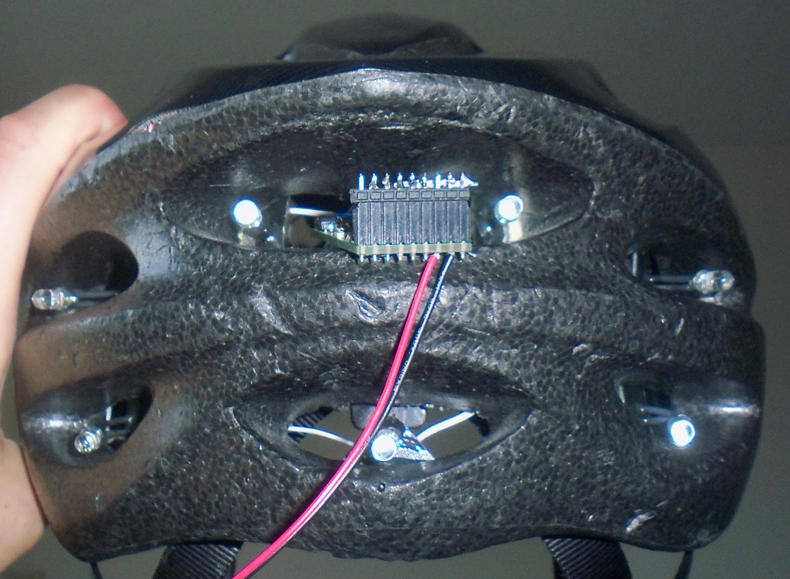
I have finally completed the bicycle helmet flasher project (that I added as an afterthought to the REM sleep mask PCB).  The design and fabrication of the controller module was outlined in a previous post; here I show the results of finally installing the lights into my existing helmet.


Additionally, the source has been slightly modified (available here); the device now has three buttons, one each for brightness of the forward and rear lights and the third setting the mode (off, both flashing, rear flashing with forward steady on).


The outside of the helmet is shown below; first from ahead, then from behind.  The LEDs are mounted within the hollows of the helmet, using folded-over staples as an initial anchor, then doused with two-part epoxy.


The helmet in action is shown below:

The helmet is shown from the inside below; the LEDs are wired in series.  The leads of the LEDs go through tough plastic strips which are anchored to the helmet with bent-up office staples; everything is further stabilized with a healthy helping of two-part epoxy.


The interface consists of three buttons adhered to the side of the helmet (visible in the video above).  Everything on the helmet should be water-proof (though the controller module and battery pack are not currently water-proofed, as they are very much prototypes).

Moving forward, I would want to optimize/shrink the controller module, and incorporate a lithium-polymer battery pack with USB charging; hopefully, this would allow the whole battery/controller module to fit within the hollows of the helmet (rather than having a tethered AA battery pack hanging off of the back, as it is currently)

Saturday, June 23, 2012

Sleep mask prototype assembly and initial testing (or, now that the hardware's built, it's only 90% of the project left to do)

The next step in the development of the Sleep Mask was fabricating the 'final' prototype, and doing some initial testing to make certain that there were no shorts.

The front and back of the assembled board (with battery and display attached) are shown below.  The smallest surface-mount parts (including the charger and headphone amplifier ICs) were placed on syringe-applied solder paste and 'baked' into place using a cheap electric skillet; the remainder of the parts were applied manually, using a conventional iron (the reason for this roundabout assembly method is detailed in a previous post; long story short, I bought the wrong paste).

Being extra-cautious, I checked each of the solder joints on the tight-pitch ICs before adding the rest of the components.  Being extra-paranoid, I introduced cuts into the power traces, so that I could monitor current usage as I re-connected different subsystems (this is evident in the backside image).

Front of assembled board; display not yet mechanically fixed
Back of assembled board; display not fixed; connector to mask lights/sensor at bottom

With everything reconnected and no programming loaded into the controller, the device drew 4.6mA; with phones plugged in (and, again, no programming and thus no signal being output), the device drew 44.5mA.  Even with the tiny battery I have connected now (450mAh), this is low enough to allow for a full night's use on a charge; of course, this doesn't take into account the power used by the IR REM sensor illuminator, the display or the extra power which may be expended to generate actual sounds with the headphones.  However, power use appears to be dominated by the audio system, so I am not too concerned right now.

I connected the assembled board to the mask (shown twice below); additionally, the display is scotch-taped to the board to secure it mechanically (but reversibly so).


The only things left for the hardware are to fix the board and battery to the mask and to install the red LEDs in the eyecups (these will be used to flash at the user during alarm conditions).  I'll also need to install a header to allow for repeated programming.  All that's left for the software... is everything.

Or course, this is the roughest sort of prototype, meant to prove the concept and develop the basic REM detection algorithms and the framework of the eventual overall program architecture.  In addition to about a million changes to the overall mechanics of the mask (formed neoprene base? injection-molded face for the buttons/display), the main board itself would undergo a lot of beneficial changes, mostly to decrease its size.  As I've commented before, the components I've used are ones I have a stock of locally; as such, they are rated for far more current/voltage/power/dissipation than needed for the current application.  Additionally, the controller is the easy-to-hand-solder TQFP, rather than the absolute smallest package available.  As a result, I suspect that a future version of the device, with all the same functionality but reduced part size, could be as small as one quarter of the area of this version.


Sunday, June 10, 2012

Project updates (or, trading a few milligrams of epidermis for a few milligrams of reflowed solder)

Due to travel (and actual, legitimate research), I've not been able to progress on these projects much in the last few weeks.  Additionally, getting the boards from Seeed took a little while (though it was worth it, 10 boards for 15$ is nothing to sneeze at; they're shown immediately below).


Today, I got back into things by trying out a little hot skillet reflow.  Going off of resources at SparkFun and this instructable, it seemed the cheapest method available to me.  To apply the paste, I didn't have the time, money or patience to do solder paste stencilling (shown in the previous links); so, I applied the paste manually, as at this site.  Unfortunately, I didn't realize that the paste formulations are different between stencil and syringe application; I loaded some stencil paste from Sparkfun (here) into a syringe and it was very tough to get it to come out.

One thing to be aware of with the stencil-type solder paste: it behaves a lot more like wet sand than any sort of easily-coaxed gel.  Syringe-type paste might behave a little better/differently.

In any event, I was able to reflow the majority of the components on the (hastily thrown together) helmet flasher board, shown below (apologies for the poor picture quality).  I have seen heating-element control boards for toaster ovens and skillets to get the perfect heat profile; in my case, cranking the thing up to max temp and waiting for the solder to turn shiny sufficed.  Note the blue wire fix; I forgot to connect the enable line for the step-up to a free pin on the controller.


Debugging revealed only two small errors in the reflow; two of the pins on the stepup controller were bridged (easily separated) and one of the resistors in the current controller didn't reflow (also easily rectified).  The step-up produces 'high voltage' (16.5V), the pots have all been manually set (one to set the high voltage level, the other two to set the maximum constant-current levels) and the controller talks to my programmer.

The next steps for this quick project are A) create a simple program for this thing, and B) assemble the in-helmet parts of the project (lights, switches and 2xAA battery pack installed, wiring routed).  There's also the more pie-in-the-sky goal of implementing the EL drivers (but I haven't quite sourced the transformers yet; not enough of my CFL bulbs have gone out yet).

Of course, just because the project has barely started doesn't mean I'm not already thinking about version 2; specifically, I'd want to implement the following changes:
A: source smaller components, with specs sized more appropriately for this project.
B: add a LiPolymer battery and charger circuit to allow the controller module to be more monolithic and allow it to be charged over micro USB.
C: figure out a better connector solution between the helmet and the controller; the 0.1" headers I'm using were chosen for inventory convenience.

Saturday, May 12, 2012

Implementation of a supervised discretization algorithm (or, I'm almost certain that I had a reason for this when I started)

Oftentimes, you have a set of data and want to use it to make a prediction about the future (e.g., predicting tomorrow's weather, based on today's weather) or about an unobserved system (e.g., predicting the presence or absence of metal ores underground, based on the local magnetic field).

In order to make that prediction, we need to set up some sort of mathematical framework describing the possible relationships between the data and the prediction.  If we have first-principles knowledge of the system under question, we can make a model of the system and use the available data to set any free parameters the model has.  However, we often have no idea about the system between the data and the prediction.  In these cases, we need to propose a sufficiently complicated and unbiased model so that, after setting the model's parameters according to the observed prediction/data relationships, the model accurately reflects the unknown system between the data and the variables to be predicted.

There is an enormous literature describing many different structures for generic predictors.  However, many of these rely on the input data being discretely-valued; that is, instead of taking on any value in a continuous range (like a distance, 12m, 5.43m, 1m, 0.333205m), they can only take on a discrete number of values (like 'number of fingers' is an integer between 0 and 12, inclusive).  In order to leverage these discrete-input predictors, it is necessary to 'discretize' continuous inputs; that is, to assign ranges of values to a single class (e.g., temperatures 0 to 10 degrees are now '0', 10 to 25 are now '1', 25 to 40 are now '2', etc.).

There is a smaller literature describing and analyzing methods for chosing how to perform this discretization.  In the future, I might put together a post reviewing these methods (at least, from a layman's perspective, as I am not a member of the machine learning research community).  Here, I will share my implementation, in MATLAB, of the method created/communicated by Marc Boulle in 2006; this was the method I found the most compelling after performing a review of the discretization literature.

The implementation

The algorithm is described (and derived, and analyzed, and experimentally compared with other methods) in "Boulle, Marc (2006). MODL: A Bayes optimal discretization method for continuous attributes. Machine Learning, 65:131-165."  The algorithm consists of a criterion which allows one to compare different potential partitionings of the data and a method for attempting to find the best partitioning, based on this criterion.

My implementation uses two 'linked lists' (in quotation marks, because they are implemented as the MATLAB generic array data type, instead of a distinct linked-list data type).  The first list contains the data on the partition intervals in the data; this information includes the total number of instances of the sample data in the interval, the number of instances of the sample data from each output class in the data, and the identity of the first an last member of the data set in each interval.  The second list points to adjacent pairs of the intervals in the first list, and is sorted according to how much the criterion would be improved by the merger of the pointed-to intervals.  The algorithm proceeds by merging the 'best' pair of adjacent intervals, then updating the lists to reflect that merger.  The algorithm is called 'greedy', as it always chooses the most immediately obvious 'best' merger, even though that may not lead to a universally optimum solution.

My implementation of this algorithm (including some support functions) is included in this archive.

A quick test

Here's some example data I generated, along with the optimal discretization returned by the algorithm (as implemented in MATLAB).  The 1000 sample data points were drawn from equal-variance gaussian distributions whose means were different and determined by their output class value.  The 1000 sample data points are plotted below; the y-axis is an individual data point's continuous value, and the point's color corresponds to its output class value.  The horizontal lines show the edges of the  intervals determined by the algorithm; as you can see, the classes (colors) are well-segregated by the edges.  Intuition suggests that there would be four edges (separating the five output classes); in the case below, there is an additional edge separating the contentious transition region between the dark blue and cyan classes.