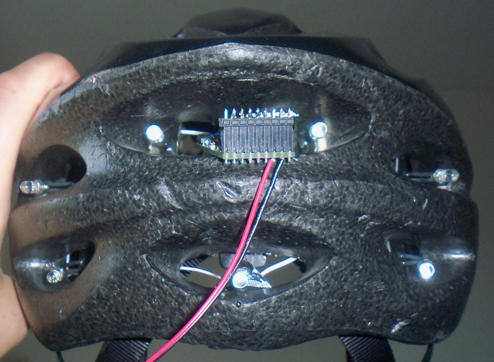
So, it recently came to my attention that I haven't posted in several months. This is due, in large part, to my actually getting work done on my PhD. This is also due to the fact that the next steps are relatively... un-glamorous and un-postable. Specifically, I have a small issue with the REM detector, and I need to figure out what's wrong with the battery charger circuit. On the up side, I was able to significantly reduce the standby power consumption of my helmet flasher so... little victories.
Charger Debugging
As it stands, the Lithium-Polymer battery charging circuit does not work. This is ironic, as it was the only sub-circuit that I did not mock up and test before ordering the circuit boards (I even mocked up the 3.3V buck converter, which only had three components). I did this because, well... I was just using the reference implementation. I've gone over the design (and the physical artifact's correspondence to it) with a fine-toothed comb; at this point, I'd like to swap the chip to see if that's the issue. Unfortunately, I do not own a hot-air rework station, so that is easier said than done. Additionally, the chip gets REALLY hot and sources a bunch of current when you plug it in, which complicates debugging, as I can only leave it plugged in for short periods. Further, even if I could simply replace the chip, I'd be leery of doing it, as the new chip could easily fry as well. This is triply annoying, as I would like to add the charger to my helmet and run signal glove in their next iteration, but can't do that until I know I've got the circuit right.
REM Detector Hiccups
The specific problem with the detector is that, for certain levels of illumination, the the detector output follows a 'negative bias' for every fourth sample; this is illustrated below. Looking at the 'noise' and mean of the signal after separating it into four down-sampled signals (that is, the first sub-signal is every four samples of the original, starting with the first sample of the whole record; the second is every four starting with the second, etc.), it appears that this really is just a constant 'bias' term added only to every fourth sample.
My current hypothesis is that this is due to my use of low-passed PWM outputs to give myself some extra low-bandwidth analog outputs to control the REM detector illumination level and the differential signal bias level. Specifically, since the sample-specific noise only occurs at certain levels of illumination, and then suddenly stops once the level raises above that level, I am lead to believe that it's something to do with the PWM switching time lining up with the ADC sampling time.
If that's the case, I'll have to decrease the passing of switching transients by reducing the corner frequency of the low-pass and/or increasing the carrier frequency of the PWM. Of course, increasing the carrier frequency will reduce the resolution of the LP-PWM channels; however, since I don't use the full resolution anyway, it wouldn't be much of a sacrifice.
Helmet flash controller standby power reduction
Going back to the helmet flasher project, I noticed that the AA batteries were getting drained in a manner that was less-than-consistent with usage. I recalled that I had been less than diligent in regards to standby power usage, so I figured I could shave off a few milliamps by taking a closer look.
There were two main methods I figured I could use to reduce standby power use: put the controller into a deeper sleep state while in standby, and modify the hardware so that I could remove power from the op-amps used int he constant-current LED drivers.
The first approach, going into a deeper sleep state, was the first I implemented since it didn't involve modifying the hardware. Before making my changes, I inserted a 1-Ohm 1% precision resistor to measure the standby current draw. I set the device to go into "power down" when going into the standby state, with wake-up accomplished by state change on any of the buttons. Additionally, I set the device to go into "standby" while the timers count and wait to move on to the next flasher state. The source is available here, in case it is useful to someone wanting to see how a non-human primate would implement the preceding.
After implementing the sleep state changes, the standby power consumption went from 2.1mA to 1.7mA. Good, but we're not finished. Since the on-state power consumption is in the range of 100-200mA, it was impossible to detect if my changes had an effect on on-state power consumption.
The next step was to switch off the power to the linear constant-current LED driver block. The op-amps used in that block draw current even when the LEDs are off, so it made sense to try to switch the power off when the device was in standby. Since the analog block was currently fed directly from the power rail, it was necessary to cut that source first.
Since the op-amps only draw a few milliamps (far less than the 30mA the controller pins are rated for), it made sense to feed them from one of the controllers output pins; this way, I didn't need to add any additional FETs. After doing this, and making the appropriate changes in the firmware, the standby power consumption fell from 1.7mA to less than 0.1mA.
Overall, these changes reduced standby power consumption from 2.1 to 0.1mA; a more than 95% reduction. This makes me much more comfortable with leaving the batteries in when I'm not using it.
Next Steps
So, the most immediate next steps involve fixing the REM detector problem outlined above and making the charger circuit work. After that, though, there are a couple of immediate next steps:
Finally finalize the sleep mask hardware
The current version of the sleep mask hardware is... clunky. Pointy. Eye-pokey, even. Since it was a first prototype, I didn't put all the effort in the world into optimizing the layout, or the parts (I just used the components I had on hand, instead of sourcing the absolute smallest I could find). Once I'm confident that the hardware is up to snuff, I can source the absolute smallest components (especially the controller and FETs/op-amps and the passives) and re-design the board. To do that, though, I need to rectify the problems listed above (REM four-sample noise, charger broken). Additionally, I'll need to take a few nights' worth of data and specify a classifier/filter that can detect 'REM' to my satisfaction; if the hardware needs revision to get to that point, I'd rather do so before the next hardware revision.
On a somewhat unrelated point, I'm going to hack up the headphone amplifier hardware to see if I can't make it more efficient. As it stands, the white noise component consumes the lion's share of the power for the device. Looking at the output of the headphone amp, the 'square edges' of the DAC output are preserved to the output; this might be causing greater power consumption than necessary. If I introduce a high-pass before the headphone amp and shave those square edges off, I might be able to significantly reduce my power consumption.
Update the helmet flasher and glove turn signal hardware; make a decision about the helmet
As I've said above, I'd like to make the turn signal glove and helmet flasher run on rechargeable lithium-polymer batteries. To do that, I need to make sure that the charger chip and circuit work as advertised.
Additionally, I need to make some decisions about the helmet flasher. As it stands, it steps the battery voltage up to 16V to drive the LEDs in series. This was done partially since I originally had intended to add some EL wire to the helmet; EL wire requires ~150V AC, and my intent was to switch current through some step-up transformers. The transformers could be smaller/have a lower turns ratio if my switched DC voltage was larger.
This step-up is expensive (3$ for the controller alone, to say nothing of the related caps and inductor). However, the series wiring of the LEDs allows the brightness/current of the LEDs to be more consistent. Maintaining the step-up would also mean that I wouldn't have to re-wire my existing helmet.
Design the sleep mask PCB version 2
As I said above, once the sleep mask hardware is finalized, I'll source smaller components, and then redesign to the circuit board. I figure it will be installed above the nose in the mask, with leads going down to the REM detector and red LEDs. I'll also incorporate power control of the analog block, as I did for the helmet above, to reduce standby power consumption.
Order new boards + components; assemble + test
Just what it says: pick the new smaller components, order them and the boards, then build everything.
Software development of the sleep mask
At this point, the hardware for the sleep mask should be more-or-less finalized. All that will be left is putting together the firmware.
I haven't given a lot of thought to the design of the interface or the overall design of the firmware. However, I have given some thought to potential features I can try out, including:
Charger Debugging
As it stands, the Lithium-Polymer battery charging circuit does not work. This is ironic, as it was the only sub-circuit that I did not mock up and test before ordering the circuit boards (I even mocked up the 3.3V buck converter, which only had three components). I did this because, well... I was just using the reference implementation. I've gone over the design (and the physical artifact's correspondence to it) with a fine-toothed comb; at this point, I'd like to swap the chip to see if that's the issue. Unfortunately, I do not own a hot-air rework station, so that is easier said than done. Additionally, the chip gets REALLY hot and sources a bunch of current when you plug it in, which complicates debugging, as I can only leave it plugged in for short periods. Further, even if I could simply replace the chip, I'd be leery of doing it, as the new chip could easily fry as well. This is triply annoying, as I would like to add the charger to my helmet and run signal glove in their next iteration, but can't do that until I know I've got the circuit right.
REM Detector Hiccups
The specific problem with the detector is that, for certain levels of illumination, the the detector output follows a 'negative bias' for every fourth sample; this is illustrated below. Looking at the 'noise' and mean of the signal after separating it into four down-sampled signals (that is, the first sub-signal is every four samples of the original, starting with the first sample of the whole record; the second is every four starting with the second, etc.), it appears that this really is just a constant 'bias' term added only to every fourth sample.
 |
| This is an example of the detector output against my hand; green is the differential signal, dark blue is the single-ended signal, and light blue/cyan is the illuminator amplitude. As you can see, the signal appears to get much more 'noisy' as the illumination level increases, until it abruptly decreases at a certain level. |
 |
| Zoomed in view of the 'noisy' segment from above; we see that the extra 'noise' is due to every fourth sample being much lower than the other three. This pattern is also borne out in the single-ended signal. |
If that's the case, I'll have to decrease the passing of switching transients by reducing the corner frequency of the low-pass and/or increasing the carrier frequency of the PWM. Of course, increasing the carrier frequency will reduce the resolution of the LP-PWM channels; however, since I don't use the full resolution anyway, it wouldn't be much of a sacrifice.
Helmet flash controller standby power reduction
Going back to the helmet flasher project, I noticed that the AA batteries were getting drained in a manner that was less-than-consistent with usage. I recalled that I had been less than diligent in regards to standby power usage, so I figured I could shave off a few milliamps by taking a closer look.
There were two main methods I figured I could use to reduce standby power use: put the controller into a deeper sleep state while in standby, and modify the hardware so that I could remove power from the op-amps used int he constant-current LED drivers.
The first approach, going into a deeper sleep state, was the first I implemented since it didn't involve modifying the hardware. Before making my changes, I inserted a 1-Ohm 1% precision resistor to measure the standby current draw. I set the device to go into "power down" when going into the standby state, with wake-up accomplished by state change on any of the buttons. Additionally, I set the device to go into "standby" while the timers count and wait to move on to the next flasher state. The source is available here, in case it is useful to someone wanting to see how a non-human primate would implement the preceding.
After implementing the sleep state changes, the standby power consumption went from 2.1mA to 1.7mA. Good, but we're not finished. Since the on-state power consumption is in the range of 100-200mA, it was impossible to detect if my changes had an effect on on-state power consumption.
The next step was to switch off the power to the linear constant-current LED driver block. The op-amps used in that block draw current even when the LEDs are off, so it made sense to try to switch the power off when the device was in standby. Since the analog block was currently fed directly from the power rail, it was necessary to cut that source first.
Since the op-amps only draw a few milliamps (far less than the 30mA the controller pins are rated for), it made sense to feed them from one of the controllers output pins; this way, I didn't need to add any additional FETs. After doing this, and making the appropriate changes in the firmware, the standby power consumption fell from 1.7mA to less than 0.1mA.
Overall, these changes reduced standby power consumption from 2.1 to 0.1mA; a more than 95% reduction. This makes me much more comfortable with leaving the batteries in when I'm not using it.
Next Steps
So, the most immediate next steps involve fixing the REM detector problem outlined above and making the charger circuit work. After that, though, there are a couple of immediate next steps:
Finally finalize the sleep mask hardware
The current version of the sleep mask hardware is... clunky. Pointy. Eye-pokey, even. Since it was a first prototype, I didn't put all the effort in the world into optimizing the layout, or the parts (I just used the components I had on hand, instead of sourcing the absolute smallest I could find). Once I'm confident that the hardware is up to snuff, I can source the absolute smallest components (especially the controller and FETs/op-amps and the passives) and re-design the board. To do that, though, I need to rectify the problems listed above (REM four-sample noise, charger broken). Additionally, I'll need to take a few nights' worth of data and specify a classifier/filter that can detect 'REM' to my satisfaction; if the hardware needs revision to get to that point, I'd rather do so before the next hardware revision.
On a somewhat unrelated point, I'm going to hack up the headphone amplifier hardware to see if I can't make it more efficient. As it stands, the white noise component consumes the lion's share of the power for the device. Looking at the output of the headphone amp, the 'square edges' of the DAC output are preserved to the output; this might be causing greater power consumption than necessary. If I introduce a high-pass before the headphone amp and shave those square edges off, I might be able to significantly reduce my power consumption.
Update the helmet flasher and glove turn signal hardware; make a decision about the helmet
As I've said above, I'd like to make the turn signal glove and helmet flasher run on rechargeable lithium-polymer batteries. To do that, I need to make sure that the charger chip and circuit work as advertised.
Additionally, I need to make some decisions about the helmet flasher. As it stands, it steps the battery voltage up to 16V to drive the LEDs in series. This was done partially since I originally had intended to add some EL wire to the helmet; EL wire requires ~150V AC, and my intent was to switch current through some step-up transformers. The transformers could be smaller/have a lower turns ratio if my switched DC voltage was larger.
This step-up is expensive (3$ for the controller alone, to say nothing of the related caps and inductor). However, the series wiring of the LEDs allows the brightness/current of the LEDs to be more consistent. Maintaining the step-up would also mean that I wouldn't have to re-wire my existing helmet.
Design the sleep mask PCB version 2
As I said above, once the sleep mask hardware is finalized, I'll source smaller components, and then redesign to the circuit board. I figure it will be installed above the nose in the mask, with leads going down to the REM detector and red LEDs. I'll also incorporate power control of the analog block, as I did for the helmet above, to reduce standby power consumption.
Order new boards + components; assemble + test
Just what it says: pick the new smaller components, order them and the boards, then build everything.
Software development of the sleep mask
At this point, the hardware for the sleep mask should be more-or-less finalized. All that will be left is putting together the firmware.
I haven't given a lot of thought to the design of the interface or the overall design of the firmware. However, I have given some thought to potential features I can try out, including:
- REM-relative wake-up alarm: only wakes you up if you are at the tail end of an REM cycle (or you've reached some no-later-then-this time). I haven't checked the science behind this, but I've heard that you wake up more refreshed if you wake up at the end of a cycle, rather than during the deep sleep in the middle.
- Sleep induction using entrainment: again, I haven't looked into how rigorous the science is behind this is, but some advocate the use of binaural beats or isochronous pulses to induce lower-frequency EEG states, assisting the user away from consciousness.
- External cues for lucid dreaming induction: the original purpose.
- Slowly increasing LED illumination to ease wake-up: just what I said, improve wake-up by gradually increasing illumination within the mask along with the natural dawn.
- REM logging: save the timestamps of REM periods, allow them to be transferred over USB. Share on facebook?
- USB bootloader: I know that Atmel provides one, I just need to see where it's hosted and play with it.