For my next project, I'm going to design and build a sleep mask that has the ability to detect rapid eye movement (REM, which indicates dreaming sleep) and present sounds and lights to the wearer to enhance the sleeping experience.
First, the device will sound an alarm when the user is at the 'optimal' time to wake up, relative to their sleep cycle. It's asserted in various places on the internet that the ideal time to wake up is at the end of an REM cycle; I'm still searching for peer-reviewed research to this effect, but there already exist devices on the market that trade on this possibly-more-substantial-than-folk wisdom. Specifically, there is a headband that records EEG (brainwaves) to detect REM sleep, and a wristwatch which detects REM through arm/body movement and/or elevated heart rate (I can't tell how exactly it detects REM from the wrist, but those are my guesses). Additionally, there are several smartphone applications and this alarm clock that detect REM through the amount of body movement a person exhibits. I will detect REM directly, by illuminating the eye with pulsed infrared light and recording the changes in the reflected power. The EEG headband device is very expensive, and my device will end up with a far wider range of features than both devices, so I don't think I'm duplicating any existing products. Additionally, the timing and duration of REM cycles will be recorded and accessible by USB.
Second, the device will present noise to the wearer to assist in sleep. I more-or-less need a 'red' noise generator running in the room to sleep well; devices on the market exist that produce white, pink and red noise as well as other 'nature' sounds to improve sleep. By generating the noise in the mask, it becomes a sort of 'best sleep in a box'; with the alarm and noise generator, you can easily have as good a night's sleep in a hotel room as you do at home. While there exist myriad smartphone programs to generate these noises (here is a site for a company that makes a good, no-nonsense one that also works for free on a computer), I don't own a smartphone. So there. Also, these features wrapped up into one common device elevates the mask to the status of a general sleep appliance that would be useful as a discrete device with one interface, one battery to charge and no monthly fee.
Third, the device will be able to deliver light and sound to the wearer during REM sleep to help induce 'lucid dreaming'. Lucid dreaming is a state where you are dreaming, but consciously aware of that fact and thus able to influence the contents and progression of the dream. The ability to dream lucidly is a talent that can be developed; one method is to train yourself to periodically perform 'reality checks' so that if you are dreaming, you will become aware of it as soon as your next 'reality check'. There are also devices which attempt to present flashes of light or sound pulses during REM sleep which can indicate to the dreamer that they are asleep. There already exists a 'commercial' product that attempts to do this called the NovaDreamer; it uses a simple delay to hopefully flash lights at the user during REM. Since this device is no longer being made, and since it uses such a simple REM prediction method (that doesn't take into account any real-time information about the user), this feature is treading in a more-or-less untapped market.
Together, these features make a device that will, hopefully, allow the user to have more enjoyable wake-ups, better sleep and possibly troubleshoot their sleep by analyzing the recorded sleep cycle data. Additionally, I will design the hardware with 'future-proofing' in mind: I will attempt to make features software-configurable and extensible so that A) features can be progressively added an debugged on the prototype hardware and B) extra features can be added beyond the immediate scope outlined above.
Overall system scope
- The most important design constraint, considering our culture's current level of microelectronic and battery technology, is device size and shape. I want this device to basically be a slightly bulky sleep mask; the battery and electronics/interface board will be mounted on the front of the eye-cups and small speakers for the noise generator will be built into the band (EDIT: this speaker-in-the-band approach has apparently been done before).
- The device should be able to run for at least three nights without recharging, and should be able to be used while charging (I absolutely loathe cordless devices that can't charge while being used; burn in hell, cheap knock-off cordless drill!).
- The interface should be quick and simple for common tasks but allow for more detailed settings to be accessed relatively easily; additionally, common during-sleep interactions like volume control and snooze should be easy to perform while wearing the device.
- Charging, sleep data downloading and firmware updating should occur through micro USB port due to the ubiquity of micro-USB cables and chargers for cellphones (and even for dumb devices, of late).
Overall system design
Mechanical
The mechanical design will consolidate as much of the electronics as possible onto a single board over the left eye; REM detection will occur through emitter/detector pair whose leads go through the left eyecup; the battery will be mounted over the right eyecup; and the speakers will be built into the sleep mask's band. Eventually it will make sense to design a hard plastic enclosure/casing for the electronics in and around the mask, but for now I'm going to focus on the electronic side of the design.
Electronic
The electronics will consist of several subsystems:
- Power management: a Microchip LiPo battery charger IC will sit between the USB V+ rail, the LiPo battery and the application circuit. Everything downstream of the battery will run off a +3.3V rail provided by a high-efficiency buck converter.


- REM detection: the center of the detector will be an IR emitter and a pair of IR phototransistors. the detectors will be stacked to allow for differential current measurement, which will be amplified by a transimpedance amplifier cascaded with an inverting gain stage. All signals will be 'unsigned' (0 to +3.3V) and full dynamic range ensured by proper biasing. This circuit is cribbed fairly liberally from an undergraduate project to implement REM detection for a sleep alarm (design document mirrored here). A similar project is here. Since the signal of interest is very low bandwidth, the emitter will be pulsed in time with ADC sampling of the output; this is a significant difference from the previous work and should result in significant power savings.

- Noise generation: an attractively-featured Maxim headphone amplifier will be fed with the DAC outputs of the microcontroller. The chosen amplifier breaks out the feedback path, allowing me to design in a suitable bandpass to cut off the high-frequency DAC switching transients and also block the +3.3/2V DC component in the DAC outputs.

- Interface: the interface will consist of four appropriately labeled pushbuttons and a nifty ultra-tiny OLED display manufactured by Univision Technology Inc.. I was able to find two for cheap off eBay; I found the module and controller datasheets on the Adafruit website (here and here). The module contains its own driver stepup and is controlled over SPI.
- Controller: ATXMEGA32A4U. I wanted built-in DACs and USB support; additionally, the timers for the ATXMEGA (along with most everything else) are very expansively featured and allow for 32MHz operation down to 2.7V. Migrating to ATXMEGA from the ATTINY and ATMEGA I've played with in the past means that I needed to find a cheap PDI programmer; I found the ZeptoProg on eBay for reasonable cheap and it plays well with AVR Studio 6 (I tried to get it to play well with AVRDUDE and the open source toolchain I used to use... but the problems have not yet been resolved).
The minimum usable endurance for the device is one night; assuming a middle-of-the-line, appropriately sized LiPo battery of 1000mAH capacity, this means that our device needs to draw about 100mA in the mean. Tallying up the current usage of the various subsystems in theory yields a number far less than this, but I want to plan for the worst in putting together the prototype. The buck can handle more than 100mA, and the battery charger circuit was designed with trimpots to allow for an appropriately-sized battery to be chosen after the completed device has been tested for real-life current usage.
Software
I've only designed the software in the broadest strokes; there will be a 'mission' mode, wherein the device keeps time, generates noise and detects REM, and an 'interface' mode, where the user is navigating menus and setting things up. The reason I plan to segregate this way is twofold: first, the user can't navigate most of the menus while wearing the device, so we'll never have to do both (generated noise/sense REM and generate the interface display); second, generating the random numbers for the noise might take up a significant fraction of the available processing power, so I want to leave as many cycles spare as I can during 'mission' operation.
For particular computational tasks, I have put together some research/notes and even performed some simulations to verify cycle costs and correct theoretical behavior. Specifically, I've collected a number of online resources toward the task of generating reasonably white noise from pseudorandom noise generators on a microcontroller substrate (8-bit XORshift, wider XORshift, linear congruential generators). Additionally, there are a couple of good online treatments of the problem of generating pink noise from white noise (here and here; while red noise is easy (just integrate), pink noise falls off as though passed through a 'half-order' filter, making the whole proposition interesting). In a future post, I'll go over these methods and the results of my simulations/implementations.
Futureproofing
I cut off the ballooning feature list as outlined above; however, there is a lot left I want to implement. Additionally, since this is a prototype, I wanted the design to be able to be implemented incrementally with the same printed circuit board; I am a poor, struggling, starving, barely-making-the-rent artist type so I really only want to order one version of the board.
For debug-proofing, the following features will be added, to allow for incremental feature roll-out
- Test pads allowing easy access to the programming port and a simple UART. This will allow for ease of programming before I figure out how to work Atmel's super nifty firmware-update-over-usb bootloader. The UART will allow for debug information to pass easily from the device, and allow for proto-interfaces to be coded for the UART before I get the real SPI-OLED interface up.
- Trimpots to set the charger IC's constant-current charge level and constant-voltage current threshold. Since the overall power usage is not 100% nailed down at this point, I wanted easy options for the battery. Additionally, this allows me to eventually make the weight/cost/benefit tradeoff without having to pull up and replace set resistors on the board.
- Pads and jumpers inline with the REM and noise signals paths. This will allow me to troubleshoot problems with those subsystems (though I hope to have the circuits finalized through practical testing before I order the boards).
- The option of a manual trimpot or microcontroller PWM control of the bias level for the REM circuit. My current plan is to use the ongoing signal levels in the REM circuit to set the bias level, allowing for greater signal amplification without running into the edge of my dynamic range. However, this may not be the best solution (or it may just take some finite time to implement), so I'm giving myself the option of manual setting via a trimpot.
As for future-proofing, there is really only one thing that I am altering the hardware for to possibly allow in the future, and that is a pulse oxygenation sensor. This sort of a sensor would allow the device to have access to both the user's pulse rate (potentially improving the REM detection) and the user's blood oxygenation (a decent measure of the efficacy/rate of their breathing). Being able to record these two things would make sleep-problem diagnosis with the device significantly more powerful. Admittedly, my current knowledge of the practical tribulations involved in building a robust pulseox sensor is minimal; however, I know that I will need an analog input, two 180-degree out-of-phase PWM signals and two analog outputs to set the emitter gains (which I will implement with lowpassed PWM signals).
Additional futureproofing would involve adding a micro SDHC card slot to allow for datalogging of more user sleep data (especially if the pulseox is ever added). Since, in terms of harware, this is as simple as connecting to an SPI port, I will add the footprint and pullup resistors at the end of the board design process if the added device size seems reasonable.
All of my other potential future features are software changes; for example, I might want to add some code to slowly bring up the visible LED levels to simulate sunrise, leading to better wake-ups. By having the LEDs driven by PWM from the start, this should not require any hardware futureproofing.
Work to date
Beyond the general design work, I've begun to mock up sub-circuits to test them and refine the design. Additionally, I've begun to modify a sleep mask with the various bits and bobs necessary to detect rapid eye movement.
I've mocked up the 3.3V buck circuit (shown below). It is able to source more than 100mA, as detailed in the data sheet. In fairness, it probably wasn't necessary to verify this simple circuit, but I had a bad time with a similar boost as part of a project during college, so I'm paranoid about switched supplies.

Here is the sleep mask with the infrared REM emitter/detectors installed; I've tried to keep as little as possible of the circuit installed on the mask. The leads from the emitter and detectors (emitter in the middle) are folded over to keep them all in place. The wires are sewn onto the mask to keep things tidy. The longer unconnected wires will eventually be trimmed and connected to a visible LED in each eyecup.


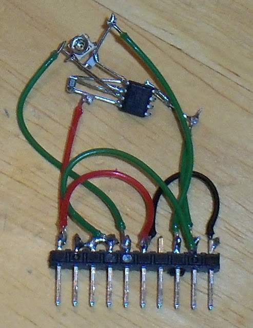
Finally, I've put together the first stage of the REM detector amplifier (shown below). I've already had to reduce the value of the transimpedance feedback resistor from what had been used before to prevent output saturation.
Next steps
The immediate next step is to take a look at the output of the mocked-up amplifier to determine the characteristics of the REM reflectance signal. My first priority is to nail down the ideal value of the transimpedance feedback resistor to allow for the largest gain without being unable to maintain the voltage between the phototransistors at 3.3V/2. Additionally, this investigation should reveal what the effective bandwidth of the signal is, informing my choice of sampling rate.
After that, I will completely specify and prototype the whole REM detector circuit. Specifically, I will try out the pulsed-emitter idea I had to reduce power consumption. It will be necessary to see how long the rise time is for the output once the emitter is activated; also, I've got to make certain that the differential output current isn't affected (beyond the obvious) by being pulsed.
Soon after (and during) those steps, I'm going to mock up the power and programming and USB lines for the ATXMEGA controller, programming it with Atmel's USB-based bootloader to make subsequent reprogramming easier. I'll also make sure that I can talk to the OLED display.
At that point, I think I'll be ready to design and purchase the boards. I still won't have prototyped the LiPo charger and headphone amplifier circuits, but these are very straightforward (and adequately datasheet-ed) and shouldn't present any surprises.
I've mocked up the 3.3V buck circuit (shown below). It is able to source more than 100mA, as detailed in the data sheet. In fairness, it probably wasn't necessary to verify this simple circuit, but I had a bad time with a similar boost as part of a project during college, so I'm paranoid about switched supplies.

Here is the sleep mask with the infrared REM emitter/detectors installed; I've tried to keep as little as possible of the circuit installed on the mask. The leads from the emitter and detectors (emitter in the middle) are folded over to keep them all in place. The wires are sewn onto the mask to keep things tidy. The longer unconnected wires will eventually be trimmed and connected to a visible LED in each eyecup.


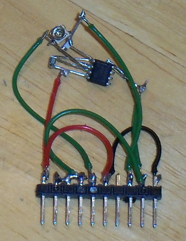
Finally, I've put together the first stage of the REM detector amplifier (shown below). I've already had to reduce the value of the transimpedance feedback resistor from what had been used before to prevent output saturation.
Next steps
The immediate next step is to take a look at the output of the mocked-up amplifier to determine the characteristics of the REM reflectance signal. My first priority is to nail down the ideal value of the transimpedance feedback resistor to allow for the largest gain without being unable to maintain the voltage between the phototransistors at 3.3V/2. Additionally, this investigation should reveal what the effective bandwidth of the signal is, informing my choice of sampling rate.
After that, I will completely specify and prototype the whole REM detector circuit. Specifically, I will try out the pulsed-emitter idea I had to reduce power consumption. It will be necessary to see how long the rise time is for the output once the emitter is activated; also, I've got to make certain that the differential output current isn't affected (beyond the obvious) by being pulsed.
Soon after (and during) those steps, I'm going to mock up the power and programming and USB lines for the ATXMEGA controller, programming it with Atmel's USB-based bootloader to make subsequent reprogramming easier. I'll also make sure that I can talk to the OLED display.
At that point, I think I'll be ready to design and purchase the boards. I still won't have prototyped the LiPo charger and headphone amplifier circuits, but these are very straightforward (and adequately datasheet-ed) and shouldn't present any surprises.


