Sunday, December 16, 2012

Replacing the middle button on the Logitech M570 Wireless Trackball (or, yes, I really do love this trackball that much)

I've been using a wireless trackball for a while now, and it's turned out to be one of the best purchases I've ever made.  It's especially excellent for working on the train, since i don't like the trackpad and there isn't room for a normal mouse.

The wireless trackball I'm using is the Logitech M570.  It has a combination scroll wheel/middle button; however, over time this button began to get flaky.  There would be weeks where the button wouldn't respond at all, or would only respond to exceptional force. Looking online, this seems to be a common problem; the device is somewhat cheaply made, and the middle button is not the usual high-performance switch, but some lower-quality part.

I set out to determine whether the button could be replaced; I was successful, and my procedure for replacing it is outlined below.  The new button is slightly stiffer than the old, but it works consistently.

Button Replacement Procedure

Disassembly

First, pop the blue trackball out.  Then, there are five screws holding the shell together; remove them.  Note that one of these screws is beneath the sticker in the battery compartment (shown below).


With the shell off, you'll need to remove the circuit boards.  First, detach the ribbon cable leading to the trackball reader (the gold bit in the middle of the image below); to do this, you'll have to pull up the plastic locking connector.  Then, remove the four screws which keep the circuit boards on the lower shell, and pick up the circuit board assembly.  Take care not to bend the battery wires as you remove them from the lower shell.  The middle/scroll wheel button we're going to replace is just in front of the ribbon cable.


Old Button Removal

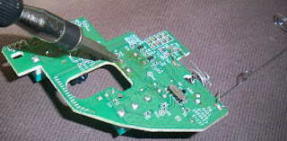
In removing the old button, we need to be careful not to damage the rest of the circuitry.  Note that our task is made easier by the fact that we don't care what state the old button ends up in.  The method I used to avoid damage to the surrounding circuit is shown below; first, I used a diagonal cutter to cut the two forward leads on the button.  Once this was done, I gently rocked the button up and down to weaken and then break the remaining two leads of the button and remove it (I did not cut these leads, as there were difficult to access without risking damage to the rest of the circuit).


Once the button is mostly removed, I used copper solder wick to clean up the four holes that the leads of the button formerly inhabited.

New Button modification and installation

If you were paying close attention during the old button removal, you'll notice that the leads were pretty much vertical.  The buttons I had on hand were very similar in size and function (normally open, leads paired length-wise); however, their leads were gull-wing SMD style (MOUSER link).  Before I can install it, I need to manipulate the leads into a more vertical configuration, detailed in pictures below.


First, push the leads down.


Then, use pliers to straighten the leads downward.


Then, gently insert the button into the cleared holes and solder it into place; be sure that it is flush with the surface of the circuit board.


Re-Assembly

Just reverse the steps in Disassembly.  It is important to make sure that the little plastic power button in the lower shell is lined up with the switch on the circuit board before screwing everything back together (the switch is the silver-and-black affair on the lower right of the picture above, just in front of where the battery clips attach to the circuit board).


It is interesting to note that Logitech uses Nordic Semiconductor radios for their wireless links (at least for the new-ish unified receiver).

Tuesday, December 11, 2012

My initial investigation of the MARLOK key (or, how many times do I have to mess up using a pipelined ADC before I'll learn my lesson permanently?)

As I mentioned in the previous post, my university uses a somewhat rare access control technology called 'MARLOK': each user is issued a key, whose identity is encoded in a series of holes in the shank of the key (kind of like an old punch-card).  The key is inserted into a reader next to a door, and if the user has privileges to the door, it is momentarily unlocked.

I was interested in reading the key (and possibly eventually building something to emulate the key, in a reader), so I had a couple of little boards made to mount infrared emitters and detectors at the appropriate distances to read the three tracks of the key.

Initial Research

Before doing all this, I tried to look up the MARLOK system on the internet.  Details were sparse; the only information of any substance is here, where someone reports that each key encodes 24 bits of ID.  Otherwise, there's very little info out there; nothing on the structure of the encoding, how the clock is embedded/recovered, etc.

The Current Test

The sensor (with key inserted) is shown below.  The emitters are Kignbright APT2012F3C; they are wired in parallel with a 460Ohm current limiting resistor, leading to a total of 5mA passing through them collectively.  The detectors are Everlight PT19-21C/L41/TR8 phototransistors; they are connected to the positive rail, and then through 2.2kOhm resistors to ground.  The voltage is sampled at the top of the resistors by a microcontroller, then sent out at 100Hz through the serial port.

The key has three tracks; the black plastic is infrared-transparent.  The metal of the key is punched with square holes to allow for IR light to travel through the key.


The ends of two of the tracks were totally accidentally exposed, to show the structure of the holes (shown below).  As you can see, the holes are square.  From the data I show later, the middle track is a clock signal; this makes sense, as the middle hole is offset from the exposed side track by a half-hole-width, so that transition on the clock track signals when to sample the data tracks.


Below is a plot of the three track traces; the left is when the sensor was seated at the base of the key, and the right occurred as I slid the sensor off the key.  Green is the middle track, red and blue are the side tracks.  Note that it took a little messing around to get this data; originally, the LED current was three times what it was for these trials, and it saturated the clock channel (since, being in the middle, it got illumination from all three LEDs).


This next is the same information, but at the end of the sensor removal, as the sensor comes of the end of the key.


From the data, I saw that the middle track was the only one that was always on; from this (and the fact that its holes were offset from the other tracks' holes), I assume it is the clock signal.

Looking at the traces over a full sensor-removal, I saw the following patterns of holes:

01111110011101
11111111111111 END OF KEY>>
00001001110111
As i said above, the middle track was the only one that was always 'on'.  Additionally, since the first clock has both 'on', and the last has both 'off', and the internet says these keys encode 24 bits, and there are 14 total clock pulses, I assume that the end-of-key data track bits are always 'on', and the base-of-key data track bits are always 'off', which likely helps in level determination and data recovery.

Moving Forward

As evidenced in the data traces, I'm having difficulty keeping the key straight in the sensor; I'll need to do something to mechanically narrow the passage.  Once this is done, it'll be possible to recover sampling times from the clock transitions.  It might also be possible to improve the signal level by masking the LEDs so that they don't bleed over into the other channels as much.

Data Recording Software

To get this data, I created a microcontroller firmware that samples the three channels, then packs each 12bit sample into a message packet (which includes a start sentinel nibble for frame alignment) and sends it over the serial port.  I then created a general-purpose serial port data-extractor and -viewer for MATLAB, which is available here.

Thursday, December 6, 2012

Final bugs and V2 (or, yes, I actually labeled the USB pins in reverse order. Stop laughing)

I've finally figured out what was wrong with the sleep mask charger and USB circuits: the pins on the connector were reversed.  So, hilariously, every time I plugged it in, i was connecting V+ and GND backwards, leading to some considerable heating in the charger IC.  Remarkably, the whole thing worked flawlessly once I flipped the connector.

Since I worked that out, I've designed version 2 of the sleep mask and helmet boards.  Additionally, I designed boards for a few other projects, including an instrumented glove, and MARLOK key reader and a pulse oximeter.  I've begun to populate the boards, but I'm out of some things, so I'm waiting for another Mouser order.  Unfortunately, the component names ended up on the silkscreen, making it thoroughly messy.

Sleep Mask V2

After figuring out what I'd done wrong with the USB connector (as well as playing around with the REM detector), I moved forward with redesigning the sleep mask controller board.  Most importantly, I significantly shrunk the board (the old version was very... clunky).  I used smaller versions of the microcontroller, FET, headphone jack and opamp.  Additionally, I added the option for a lowpass between the microcontroller DACs and the headphone amplifier, in the hopes that I can reduce power consumption.


I also wired up a new mask (the old one was... clunky.  Also gaudy... very gaudy).


Helmet V2

The new version of the helmet implemented the analog-power-off changes, in addition to adding a charger circuit.  However, it ends up being about the same size of the old board, owing to the use of smaller FET, opamp and microcontroller.


Instrumented Glove

I've long been interested in the idea of a joint-angle-sensing glove for computer interface.  Additionally, I overheard someone around the lab implying that they would like to take such joint data over a whole day of normal hand-use.  So, I thought that I could use some of the spare board-space on a circuit which would read at least 22 channels of joint angle data, and record them to an SD card.  The flex sensors will be home-made, and will change their resistance with flexion (like in this article).

I decided to go for a controlled-current topology for resistor-sensing (rather than a divider) to get a linear read on the resistance.  The resistor sensors are connected to the header at the top of the board; they connect to V+ on one side, and to the constant-current sink on the other side, through a matrix of FET switches; 5 banks of 5 sensors each give me 25 potential sensor channels for a mere 10 digital outputs.  This circuit also includes a battery charger.


MARLOK key reader

I've long hated the MARLOK key; it seems like a perfect storm of high-cost and low-convenience and I don't understand why you would use it instead of an iButton system or RFID.  In any event, I have a MARLOK key and I was curious about how the information (and clock) were encoded in it.  There isn't much information online about the format; all I was able to find was that the information is encoded in the sequence of holes drilled in the shaft of the key.

I designed a pair of board upon which I could mount IR emitters and IR phototransistors to read all three tracks of the key; I added a few spare holes to weld the two sides together using wire scraps.


Pulse Oximeter Sensor

Finally, I wanted to try out reading pulse (and possibly blood oxygenation) non-invasively.  I created a sensor board based on "A wireless reflectance pulse oximeter with digital baseline control for unfiltered photoplethysmograms" by Kejia Li and Steve Warren.  The sensor is reflectance-mode, which means that you only need access to the surface of the body; in opposition to the transmission mode, where the emitter is opposite a protruding bit of anatomy (like a finger) from the detector.  The emitters and detectors are in the upcoming order, so it's just the board and cable for now.